PROJECT 02 · IoT / EMBEDDED SYSTEM / GREEN BUILDING
02
IoT SMART
WATERING &
PLANT MONITORING
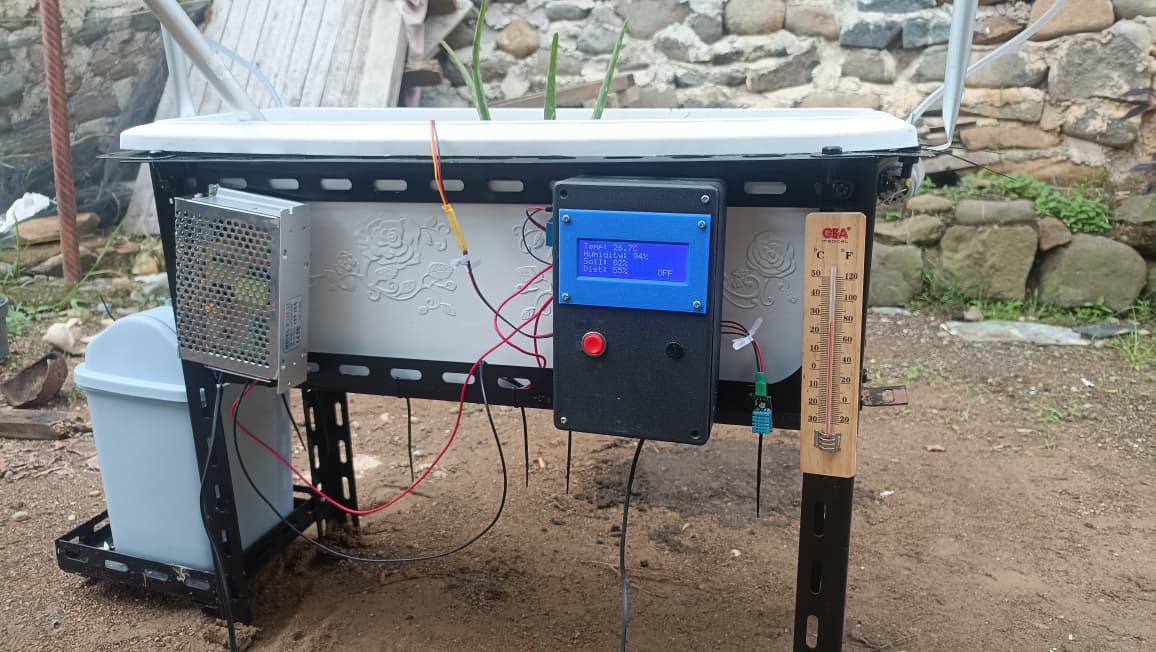
An ESP32-based irrigation and monitoring prototype that reads soil moisture, ambient temperature/humidity and tank level, controls a 12 V water pump automatically or manually, synchronizes data through Firebase Realtime Database, and provides remote plant observation using ESP32-CAM.
01 / PROJECT CONTEXT
WHY SMART WATERING FOR GREEN BUILDING?
Green-building vegetation needs reliable maintenance while water use should remain efficient. The project combines automatic irrigation with remote monitoring so watering decisions are based on measured plant and environmental conditions instead of fixed manual routines.
Plant care in green-building areas can be inconsistent when watering, tank level and plant condition are checked manually.
Use ESP32 as the local controller, read environmental sensors, automate the pump through a relay, synchronize data to Firebase and provide a mobile interface.
Prototype-scale implementation using Wi-Fi. Plant images are used for visual observation only; no computer-vision diagnosis is performed.
02 / ENGINEERING SCOPE
HARDWARE, CONTROL, CLOUD & USER INTERFACE
The project integrates sensing, actuation, local feedback, cloud data exchange and mobile interaction in one workflow. Automatic operation is based on sensor thresholds, while manual control remains available through the application and local push button.
Capacitive soil moisture, DHT11 ambient temperature/humidity, HC-SR04 tank-level measurement and ESP32-CAM visual monitoring.
ESP32 evaluates sensor data, switches the relay and 12 V water pump, drives the buzzer and updates the local LCD.
Wi-Fi connection to Firebase Realtime Database for sensor-data synchronization and remote control commands.
MIT App Inventor displays temperature, humidity, soil moisture, tank level and pump controls, with camera access for visual monitoring.
03 / SYSTEM ARCHITECTURE
SENSORS → ESP32 → ACTUATORS + FIREBASE → MOBILE USER
The local controller reads environmental and tank data, makes watering decisions, drives the pump and local indicators, and exchanges data with Firebase over Wi-Fi. The mobile application reads synchronized values and sends manual pump commands.
04 / HARDWARE INTEGRATION
ONE CONTROLLER, MULTIPLE INPUTS & OUTPUTS
Capacitive Soil Moisture
Analog soil-moisture input on ESP32 GPIO 34; used as the main trigger for irrigation demand.
DHT11
Reads ambient temperature and humidity through GPIO 4 for environmental monitoring.
HC-SR04 Ultrasonic
Trigger on GPIO 12 and Echo on GPIO 13; estimates water level in the storage tank.
Relay + 12 V Pump
Relay input on GPIO 2 switches the water pump. The actuator irrigates the planter when the control condition is met.
Local Interface
16×2 I²C LCD uses SDA GPIO 21 and SCL GPIO 22. Push button on GPIO 14 provides local manual control, while buzzer on GPIO 27 gives tank-level warning.
05 / CONTROL LOGIC
AUTOMATIC WHEN NEEDED, MANUAL WHEN REQUIRED
01
AUTOMATIC MODE
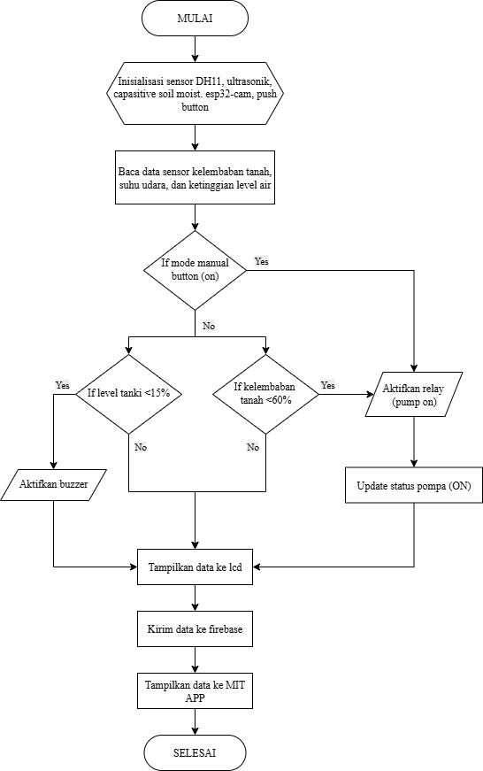
The documented flowchart uses soil moisture below 60% as the irrigation trigger. When the condition is satisfied, ESP32 activates the relay and pump; the status is then updated and sent to the monitoring layer.
02
LOW-TANK ALERT
The system monitors tank level with the ultrasonic sensor. The documented flowchart uses a low-tank threshold below 15% to activate the local buzzer and prompt refilling.
03
MANUAL MODE
A local push button can override automatic logic, while the MIT App also provides pump ON/OFF controls for remote operation and system checks.
04
LOCAL + REMOTE FEEDBACK
Temperature, humidity, soil moisture, tank level, pump state and mode are available locally on the LCD and remotely through the IoT application.
06 / CLOUD & MOBILE MONITORING
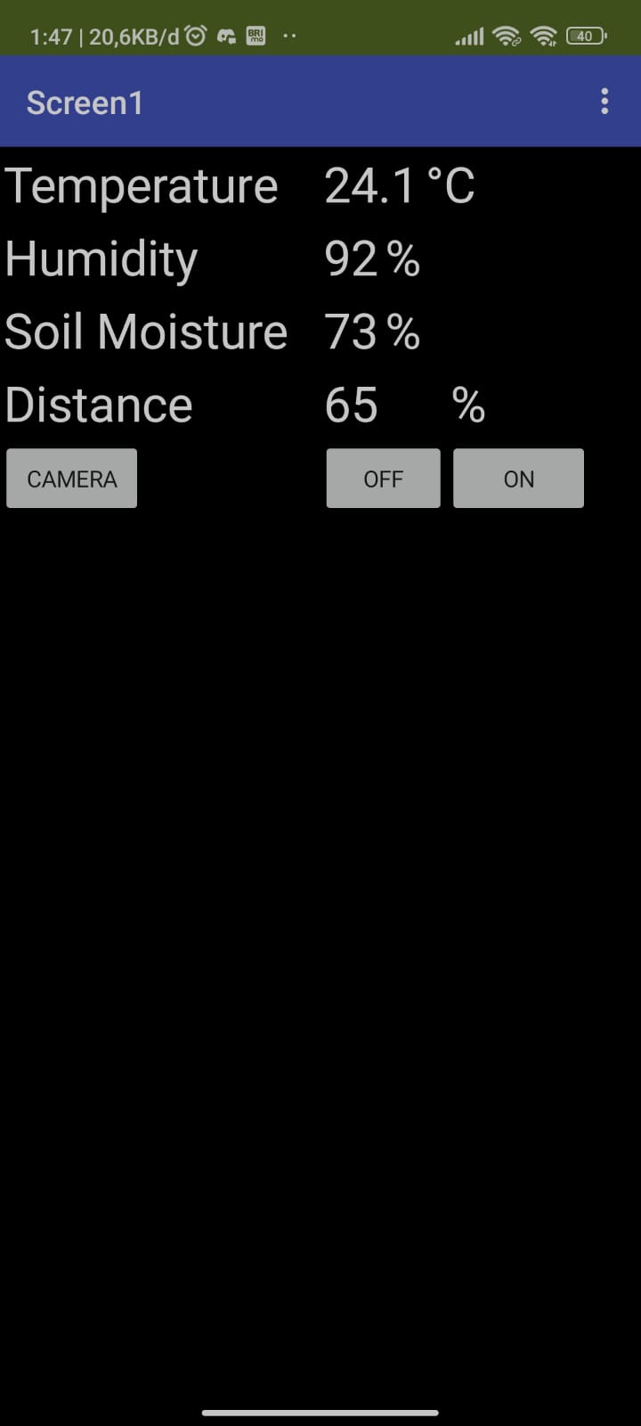
FIREBASE REALTIME DATABASE + MIT APP INVENTOR
- 01 / CONNECTESP32 connects to Wi-Fi before sending project data to the online database.
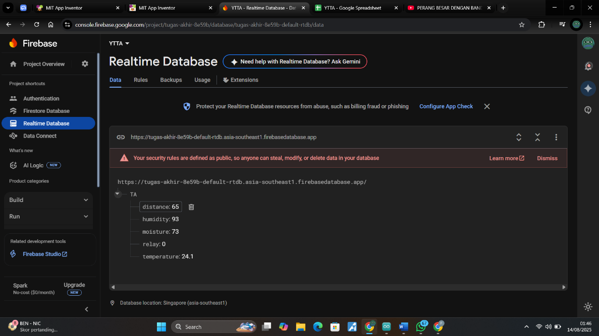
- 02 / UPLOADTemperature, humidity, soil moisture, tank level and pump status are synchronized through Firebase Realtime Database.
- 03 / DISPLAYThe Android interface displays live sensor values for remote monitoring.
- 04 / CONTROLThe ON/OFF controls allow manual pump operation when manual mode is required.
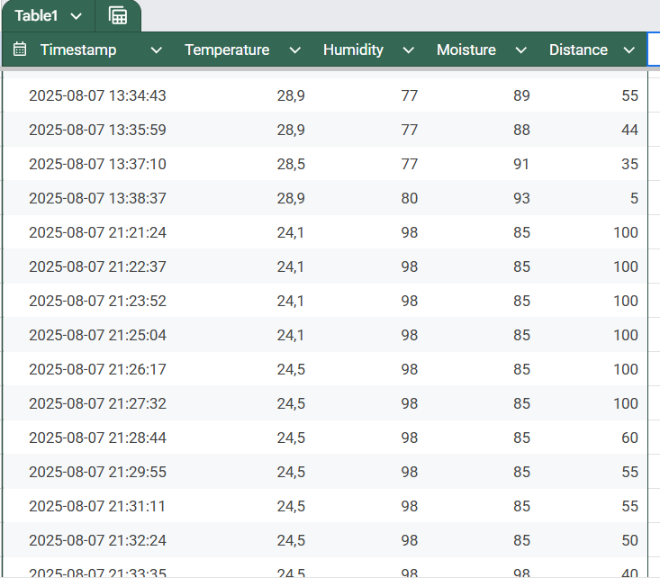
- 05 / RECORDTest data can also be stored in spreadsheet form for offline review and analysis.
07 / MECHANICAL DESIGN
PROTOTYPE BUILT AROUND A COMPACT PLANTER
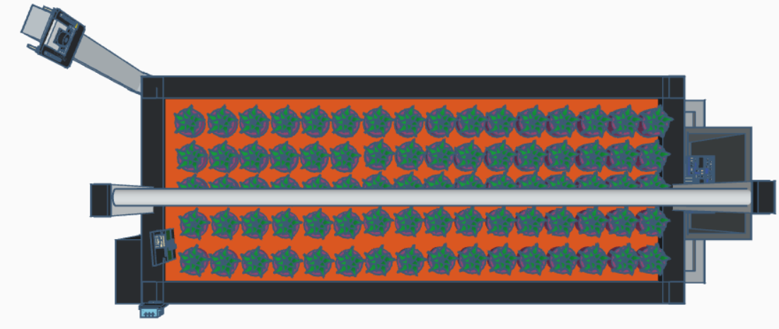
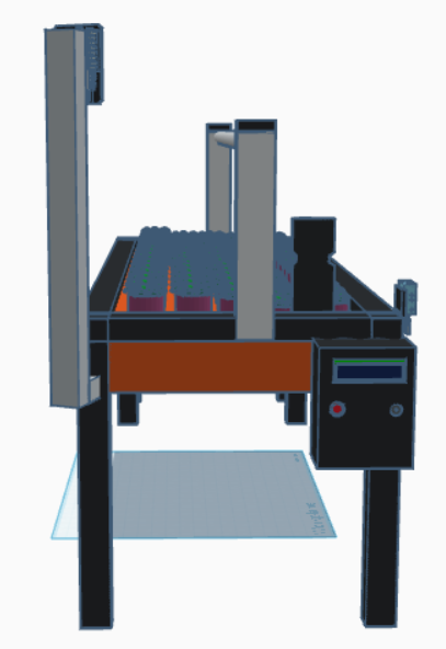
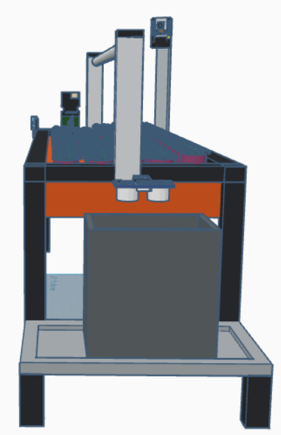
The documented frame is approximately 67 × 28 × 50 cm, supporting a 59.5 × 20 × 23 cm planting container. A 73 cm irrigation line distributes water across the planter. The left side houses the local control box and 45 cm ESP32-CAM stand, while the right side carries the water tank and level sensor.
08 / SENSOR VALIDATION
COMPARISON TESTING ACROSS FOUR SENSOR FUNCTIONS
The uploaded report documents 30 comparison trials for temperature, humidity, capacitive soil moisture and ultrasonic distance measurements. The resulting average error values were used to evaluate measurement consistency before system-level testing.
Average error against a thermohygrometer.
Average error against a thermohygrometer.
Average error against a three-way soil meter.
Average distance error against manual measurement.
09 / END-TO-END BEHAVIOR
THE PUMP RESPONDS TO ACTUAL SOIL CONDITIONS
Soil moisture fell below the automatic threshold. The pump remained active at 46%, then stopped after moisture rose to 75%.
After the watering cycle, soil moisture increased to 85% and the pump returned to OFF.
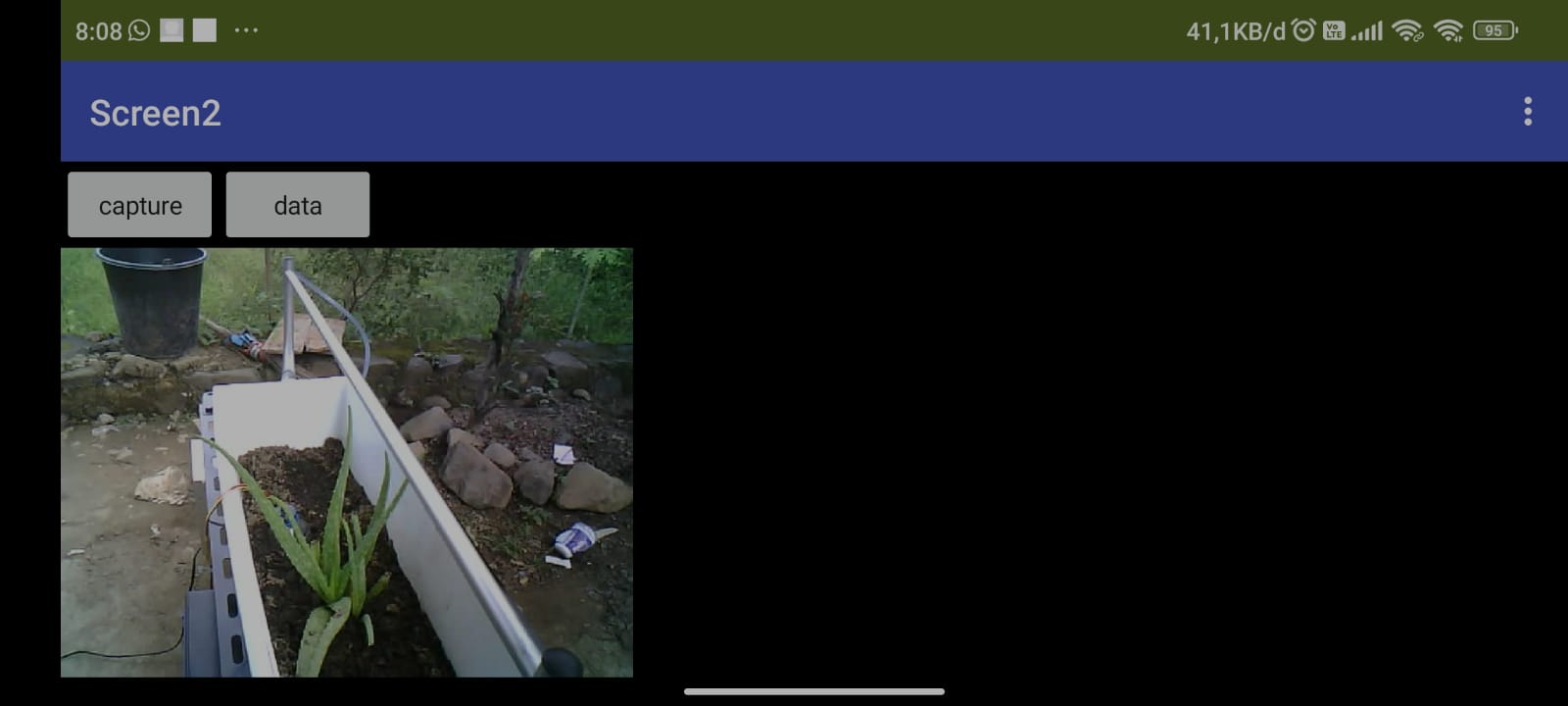
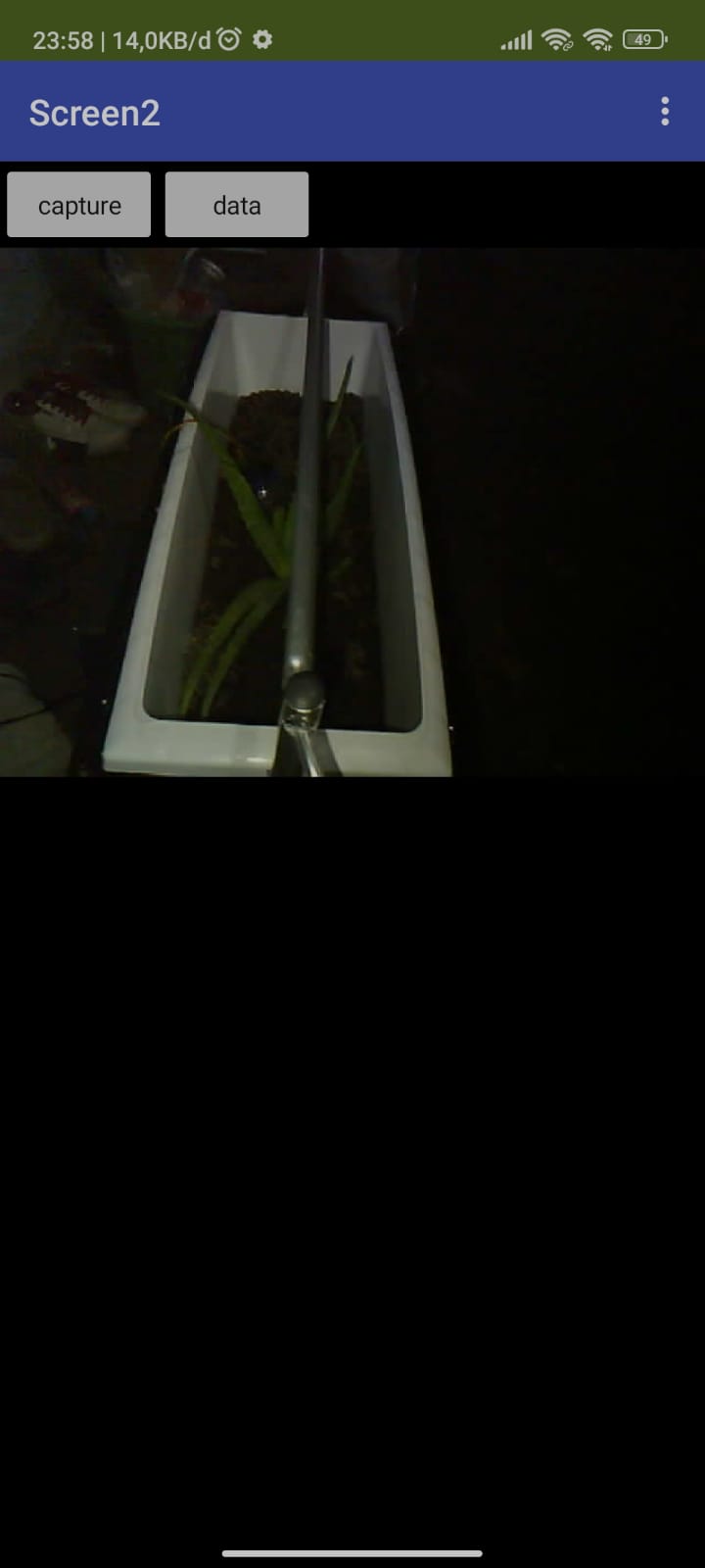
ESP32-CAM was evaluated in morning, midday, afternoon and night conditions. Image quality dropped significantly at night because of limited illumination.
The report concludes that the system maintained post-watering soil moisture around 75–85% in the recorded tests and that the 60% threshold was suitable for the prototype conditions.
10 / LIMITATIONS & NEXT DEVELOPMENT
WHAT I WOULD IMPROVE NEXT
Night-time plant images lose detail. A better camera or dedicated white illumination would improve remote visual inspection.
The current prototype warns the user when water is low. The next iteration could add automatic refill control and additional fail-safe level sensing.
Capacitive soil-moisture error increased in very dry conditions. Further calibration with the target soil medium would improve precision.
The implementation depends on Wi-Fi and Firebase. Local buffering, reconnect logic and offline-safe control would increase robustness.